If you were to try to simply spot a GPS signal at 1.575 GHz in the spectrum on a waterfall in a program like SDR# you would probably fail to see anything. This is because GPS signals are very weak, and operate below the thermal noise floor. Only through clever processing algorithms can the actual signal be recovered.
With real data passed through the fast autocorrelation block he is able to observe GPS signal peaks that occur every millisecond. E.p. explains the reason for this:
Why every millisecond? The coarse/acquisition code for GPS (C/A) has a period of 1023 chips which are transmitted at a rate of 1.023 MBit/s. This results in period of 1 millisecond. BAM!
Over on the SDRGPS blog Philip Hahn and fellow aerospace engineer Paul Breed have been working together to try and use an RTL-SDR to help get accurate GPS data for tracking small high powered rockets. They write that their end goal is to be able to “track high power rockets in high acceleration / speed / altitude environments”.
In their latest attempt they launched a rocket with an RTL-SDR on board with it capturing GPS data to be later processed with GNSS-SDR. The goal was to get a GPS fix throughout the flight. Unfortunately they found that a good fix was only obtained while the rocket was on the ground, and not much data was obtained while it was in the air. They write that they suspect that the fault lies in the vibration in the rocket which can affect the frequency stability of the crystal oscillator, or in the GPS satellite tracking loop algorithm.
They still hope to be able to get some usable information from the flight by trying other algorithms on the data, but they are also seeking advice from anyone who might know how to help them, so please contact them if you know anything that may help.
Back in April we posted about Philip Hahn and Paul Breed’s experiments to use an RTL-SDR for GPS logging on their high powered small rockets. As GPS is owned by the US military, a standard GPS module cannot be used on a rocket like this, as they are designed to fail if the GPS device breaches the COCOM limit, which is when it calculates that it is moving faster than 1,900 kmph/1,200 mph and/or higher than 18,000 m/59,000 ft. The idea is that this makes it harder for GPS to be used in non-USA or home made intercontinental missiles. As SDR GPS decoders are usually programmed in open source software, there is no need for the programmers to add in these artificial limits.
In their last tests they managed to gather lots of GPS data with an RTL-SDR, but were only able to decode a small amount of it with the GNSS-SDR software. In this post Philip discoversa flaw in the way the GNSS-SDR performs acquisition and retrackingthat GNSS-SDR decodes in such a way that makes it difficult to obtain a location solution with noisy high-acceleration data. By using a different GPS implementation coded in MATLAB, he was able to get decoded GPS data from almost the entire ascent up until the parachutes deploy. Once the parachutes deploy the GPS has a tough time keeping a lock as it sways around. His post clearly explains the differences in the way the code is implemented in GNSS-SDR and in the MATLAB solution and shows why the GNSS-SDR implementation may not be suitable for high powered rockets.
In addition, they write that while the flight was just under the artificial COCOM GPS fail limits for speed and height, the commercial GPS solution they also had on board failed to collect data for most of the flight too. With the raw GPS data from the RTL-SDR + some smart processing of it, they were able to decode GPS data where the commercial solution failed.
GPS data acquired from the RTL-SDR on the rocket (blue line shows solution from MATLAB code, yellow shows GNSS-SDR solution, and red shows commercial GPS receiver solution).
In previous posts we showed how Phillip Hahn had been trying to use his RTL-SDR as a GPS receiver on a high powered rocket in order to overcome the COCOM limits which prevent commercial GPS devices from operating when moving faster than 1,900 kmph/1,200 mph and/or higher than 18,000 m/59,000 ft.
In order to test future flights with the RTL-SDR GPS receiver, Phillip has been simulating GPS rocket trajectory signals and using his LimeSDR. The RTL-SDR then receives the simulated GPS signals which are then fed into SoftGNSS for decoding. The simulation simulates the Japanese SS-520-4 rocket which is a 32′ long, 2′ diameter small high powered rocket capable of putting loads like cubesats into orbit affordably. Using the simulated data Phillip is able to calculate the trajectory and see all the motor burns in the velocity profile.
While Phillip intends to use the RTL-SDR on a similar rocket in the future, he notes that the simulation does not take into account problems such as thermal noise, or RF interference, rocket jerk, satellite occlusion and vibration problems.
LimeSDR Simulated GPS Rocket Trajectory Received with RTL-SDR.
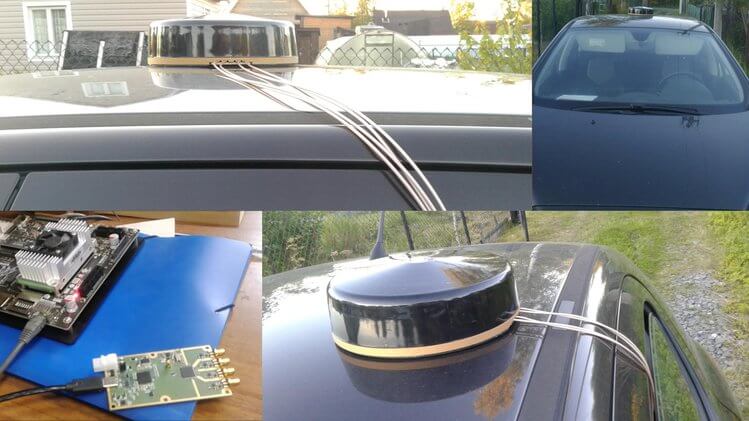
The RTL-SDR can be used to receive, decode and plot Global Positioning System (GPS) data in real time. To do this the RTL-SDR must be connected to a GPS antenna.
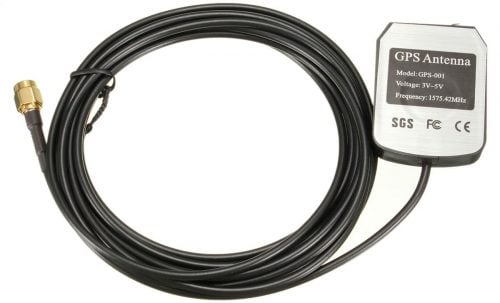
Extremely cheap $5 or less active GPS antennas with SMA connectors can be found on eBay, Amazon or Aliexpress. These GPS antennas contain a small ceramic patch antenna, a low noise amplifier and a GPS filter. In order to power the LNA in the antenna, you’ll need to have an RTL-SDR with bias tee. Our RTL-SDR.com V3 dongles have this feature built in, but if you don’t have a V3 you could also use a homebrew 5V external bias tee module or hack it into a standard RTL-SDR if you desired.
Also note that most standard R820T/2 RTL-SDRs fail to receive after a few minutes at frequencies above about 1.3 GHz due to heat issues. Our RTL-SDR.com V3 dongles don’t have this problem in most climates thanks to the metal case cooling and improved thermal design on the PCB. If you experience this problem it can also be alleviated by using the special L-Band RTL-SDR drivers.
A typical $3 GPS antenna
The main GPS frequency is 1.575420 GHz, but most of this signal is very weak and below the noise floor. If you were try to view the spectrum of GPS in SDR# you will find that you won’t see much other than perhaps a very weak hump. Only through clever signal processing is such a weak signal actually recovered. Below we show screenshots of the GPS spectrum as seen by an RTL-SDR and more wideband Airspy R2 SDR.
GPS RTL-SDR
GPS Airspy
The following tutorial shows how to receive and decode GPS signals and get a coordinate on a map of your location, using only an RTL-SDR dongle (with bias tee) and GPS antenna. This tutorial is based heavily on Philip Hahn’s blog post at sdrgps.blogspot.com/2015/12/first-proof-of-concept-gps-fix-in.html.
Download GNSS-SDRLIB from github.com/taroz/GNSS-SDRLIB. On GitHub click on the green “Clone or download” button on the right and then click “Download ZIP”. Extract the zip file into a convenient folder on your PC. If you want to use the modified L-band drivers, copy the modified rtlsdr.dll into the the bin folder.
Make sure your RTL-SDR is plugged in, and that the bias tee has been activated (V3 software for activating the bias tee, see feature 2).
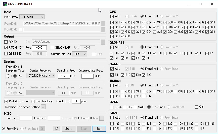
In the GNSS-SDRLIB folder, open gnss-sdrgui.exe. This will be stored in the bin subfolder.
Now set the following parameters:
Change the Input Type to RTL-SDR
Place a check next to RTCM MSM , and set the Port to 9999.
Ensure that “Output Interval” is set to 10Hz.
Ensure that “Plot Acquisition” and “Plot Tracking” are both checked.
Under “MISC” optionally enter your approximate latitude and longitude to help with getting an initial lock..
Under the GPS, GLONASS and Galileo headings ensure that the “ALL”
Apply appropriate settings in GNSS-SDRLIB GUI
Press Start. A bunch of command windows will begin opening and closing for a few seconds. After that, a bunch of gnuplot graph windows will open up. These can be ignored.
Next go to the extracted RTK-NAVI folder, and enter the bin directory. Open the rtlnavi.exe file.
Click on the “I” button in the upper right region.
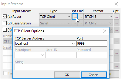
Place a check mark next to (1) Rover, and change the “Type” to TCP Client, and the “Format” to RTCM3. Click on the button with three dots under the leftmost “Opt” and set the “TCP Server Address” to localhost, and the “Port” to 9999. Press the OK button to exit the two windows.
Set the input stream
Now press Start in RTK-NAVI.
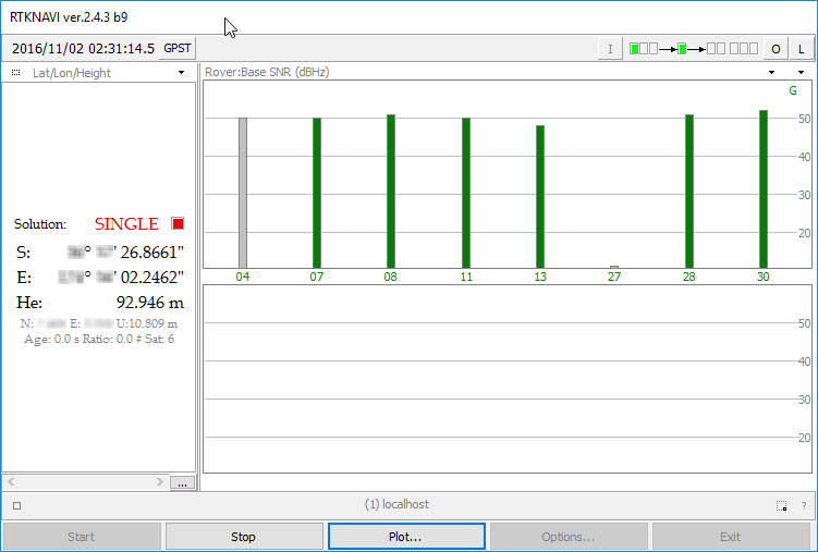
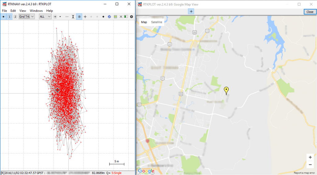
You should now see several bars in the top graph. These bars show GPS signal strengths for satellites. After a short time you should see a solution in the left panel which will be your current coordinates. If no solution ever comes, try respositioning your GPS antenna for a better view of the sky, and double checking that the bias tee is activated. Sometimes simply restarting GNSS-SDRLIB can fix no solution being found.
Check reception and wait for GPS lock solution.
In RTK-NAVI click on the “Plot” button. This will open a positional plot of the recorded coordinates. To view your position on a Google map, click View → Google Map View. If everything is working correctly you should now be seeing an accurate marker of your current location.
Back in April and July of last year we posted about Philip Hahn and Paul Breed's experiments to use an RTL-SDR for GPS logging on their high powered small rockets. Basically they hope to be able to use an RTL-SDR combined with a computing platform like a Raspberry Pi or Intel Compute stick and software like gnss-sdr to record GPS data on their rocket. Using an RTL-SDR would get around the COCOM limits that essentially stop GPS from working if it measures faster than 1,900 kmph/1,200 mph and/or higher than 18,000 m/59,000 ft.
In the past they've been able to get usable data from the flights, but have had trouble with reliability and noise. That said they also tried commercial GPS solutions which have also failed to work properly even on flights travelling under the COCOM limits, whereas the RTL-SDR actually got data that could still be post processed.
If you are interested in a full summary of Phillip and Paul's experiments, then the GNU Radio blog has a nice summary written by Phillip that explains their full journey of trying to get a working RTL-SDR based GPS system for their rockets.
Rocket Trajectory as measured by the RTL-SDR based GPS receiver.
Judging from the blurb and released contents the book will be an excellent introduction to anyone interested in today's wireless security issues. They cover topics such as RFID, Bluetooh, ZigBee, GSM, LTE and GPS. In regards to SDRs, the book specifically covers SDRs like the RTL-SDR, HackRF, bladeRF and LimeSDR and their role in wireless security research. They also probably reference and show how to use those SDRs in the chapters about replay attacks, ADS-B security risks, and GSM security.
The book is yet to be released and is currently available for pre-order on Amazon or Springer for US$59.99. The expected release date is May 9, 2018, and copies will also be for sale at the HITB SECCONF 2018 conference during 9 - 13 April in Amsterdam.
The blurb and released contents are pasted below. See their promo page for the full contents list:
This book discusses the security issues in a wide range of wireless devices and systems, such as RFID, Bluetooth, ZigBee, GSM, LTE, and GPS. It collects the findings of recent research by the UnicornTeam at 360 Technology, and reviews the state-of-the-art literature on wireless security. The book also offers detailed case studies and theoretical treatments – specifically it lists numerous laboratory procedures, results, plots, commands and screenshots from real-world experiments. It is a valuable reference guide for practitioners and researchers who want to learn more about the advanced research findings and use the off-the-shelf tools to explore the wireless world.
Authors:
Qing YANG is the founder of UnicornTeam & the head of the Radio Security Research Department at 360 Technology. He has vast experience in information security area. He has presented at Black Hat, DEFCON, CanSecWest, HITB, Ruxcon, POC, XCon, China ISC etc.
Lin HUANG is a senior wireless security researcher and SDR technology expert at 360 Technology. Her interests include security issues in wireless communication, especially cellular network security. She was a speaker at Black Hat, DEFCON, and HITB security conferences. She is 360 Technology’s 3GPP SA3 delegate.
This book is a joint effort by the entire UnicornTeam, including Qiren GU, Jun LI, Haoqi SHAN, Yingtao ZENG, and Wanqiao ZHANG etc.
The LA Times recently ran a story that discussed how vulnerable GPS is to malicious spoofing. This has been well known for a number of years now with researchers having been successful at diverting a 80-million dollar yacht off it's intended course 5 years ago. We've also seen GPS spoofing performed with low cost TX capable SDRs like the HackRF. For example we've seen researchers use GPS spoofing to cheat at "Pokemon Go" an augmented reality smartphone game and to bypass drone no-fly restrictions.
The article in the LA times also discusses how a group of researchers at Aerospace Corp. are testing GPS alternatives and/or augmentations, that improve resilience against spoofing. The system being developed is called 'Sextant', and it's basic idea is to use other sources of information to help in determining a location.
Other sources of information include signals sources like radio, TV and cell tower signals. It also includes taking data from other localization signals like LORAN (a long range HF based hyperbolic navigation system), and GPS augmentation satellites such as the Japanese QZSS which is a system used to improve GPS operation in areas with dense tall buildings, such as in many of Japans cities. More advanced Sextant algorithms will possibly also incorporate accelerometer/inertial data, and even a visual sensor that uses scenery to determine location.
Most likely a key component of Sextant will be the use of a software defined radio and from the photos in the article the team appear to be testing Sextant with a simple HackRF SDR. While we're unsure of the commercial/military nature of the software, and although probably unlikely, hopefully in the future we'll see some open source software released which will allow anyone to test Sextants localization features with a HackRF or similar SDR.
The NT1065 is an all-in-one 4-channel global navigation satellite system (GNSS) receiver chip. It is highly versatile and can receive and decode multiple navigation satellites such as GPS, GLONASS, Galileo, BeiDou, IRNSS and QZSS. Being able to receive so many satellites, it is capable of centimeter level positioning.
The team at Amungo Navigation have taken this chip and have created a product called the NUT4NT+ which is essentially a development board for the NT1065, and all the software for signal processing with it is provided as open source software. In the near future they are planning to begin fundraising for the product over on the crowd funding site CrowdSupply.
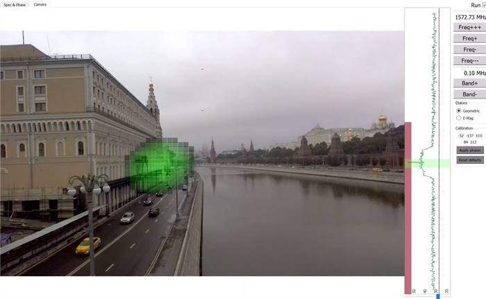
One very interesting application that they have been developing with a device similar to the NUT5NT+ is a GPS Jammer/Spoofer detector system which they call the Amungo XNZR. This is a combined 4-channel GNSS receiver and 4-antenna GNSS antenna system built into a small package that fits onto the back of an Android tablet. When connected to the software it uses augmented reality (AR) to show you exactly where GPS jammers are in the vicinity by using coherent signal processing. If you're not familiar with AR, this is the technique of overlaying digital data/images on top of a live real world camera view.
Detecting a Kremlin GPS Spoofer in Augmented Reality
In the video below they take their XNZR detector to Varvarka Street in Moscow Russia and determine the location of a GPS spoofer in the vicinity.
More information about their product can be found on their homepage, and on various interesting forum posts by someone from the company that detail some of their experiments. Note that the forum posts are in Russian, but Google Translate can be used to translate the text.
Over on the SDRGPS blog Philip Hahn and fellow aerospace engineer Paul Breed have been working together to try and use an RTL-SDR to help get accurate GPS data for tracking small high powered rockets. They write that their end goal is to be able to “track high power rockets in high acceleration / speed / altitude environments”.
In their latest attempt they launched a rocket with an RTL-SDR on board with it capturing GPS data to be later processed with GNSS-SDR. The goal was to get a GPS fix throughout the flight. Unfortunately they found that a good fix was only obtained while the rocket was on the ground, and not much data was obtained while it was in the air. They write that they suspect that the fault lies in the vibration in the rocket which can affect the frequency stability of the crystal oscillator, or in the GPS satellite tracking loop algorithm.
They still hope to be able to get some usable information from the flight by trying other algorithms on the data, but they are also seeking advice from anyone who might know how to help them, so please contact them if you know anything that may help.
Back in April we posted about Philip Hahn and Paul Breed’s experiments to use an RTL-SDR for GPS logging on their high powered small rockets. As GPS is owned by the US military, a standard GPS module cannot be used on a rocket like this, as they are designed to fail if the GPS device breaches the COCOM limit, which is when it calculates that it is moving faster than 1,900 kmph/1,200 mph and/or higher than 18,000 m/59,000 ft. The idea is that this makes it harder for GPS to be used in non-USA or home made intercontinental missiles. As SDR GPS decoders are usually programmed in open source software, there is no need for the programmers to add in these artificial limits.
In their last tests they managed to gather lots of GPS data with an RTL-SDR, but were only able to decode a small amount of it with the GNSS-SDR software. In this post Philip discoversa flaw in the way the GNSS-SDR performs acquisition and retrackingthat GNSS-SDR decodes in such a way that makes it difficult to obtain a location solution with noisy high-acceleration data. By using a different GPS implementation coded in MATLAB, he was able to get decoded GPS data from almost the entire ascent up until the parachutes deploy. Once the parachutes deploy the GPS has a tough time keeping a lock as it sways around. His post clearly explains the differences in the way the code is implemented in GNSS-SDR and in the MATLAB solution and shows why the GNSS-SDR implementation may not be suitable for high powered rockets.
In addition, they write that while the flight was just under the artificial COCOM GPS fail limits for speed and height, the commercial GPS solution they also had on board failed to collect data for most of the flight too. With the raw GPS data from the RTL-SDR + some smart processing of it, they were able to decode GPS data where the commercial solution failed.
GPS data acquired from the RTL-SDR on the rocket (blue line shows solution from MATLAB code, yellow shows GNSS-SDR solution, and red shows commercial GPS receiver solution).
In previous posts we showed how Phillip Hahn had been trying to use his RTL-SDR as a GPS receiver on a high powered rocket in order to overcome the COCOM limits which prevent commercial GPS devices from operating when moving faster than 1,900 kmph/1,200 mph and/or higher than 18,000 m/59,000 ft.
In order to test future flights with the RTL-SDR GPS receiver, Phillip has been simulating GPS rocket trajectory signals and using his LimeSDR. The RTL-SDR then receives the simulated GPS signals which are then fed into SoftGNSS for decoding. The simulation simulates the Japanese SS-520-4 rocket which is a 32′ long, 2′ diameter small high powered rocket capable of putting loads like cubesats into orbit affordably. Using the simulated data Phillip is able to calculate the trajectory and see all the motor burns in the velocity profile.
While Phillip intends to use the RTL-SDR on a similar rocket in the future, he notes that the simulation does not take into account problems such as thermal noise, or RF interference, rocket jerk, satellite occlusion and vibration problems.
LimeSDR Simulated GPS Rocket Trajectory Received with RTL-SDR.
The RTL-SDR can be used to receive, decode and plot Global Positioning System (GPS) data in real time. To do this the RTL-SDR must be connected to a GPS antenna.
Extremely cheap $5 or less active GPS antennas with SMA connectors can be found on eBay, Amazon or Aliexpress. These GPS antennas contain a small ceramic patch antenna, a low noise amplifier and a GPS filter. In order to power the LNA in the antenna, you’ll need to have an RTL-SDR with bias tee. Our RTL-SDR.com V3 dongles have this feature built in, but if you don’t have a V3 you could also use a homebrew 5V external bias tee module or hack it into a standard RTL-SDR if you desired.
Also note that most standard R820T/2 RTL-SDRs fail to receive after a few minutes at frequencies above about 1.3 GHz due to heat issues. Our RTL-SDR.com V3 dongles don’t have this problem in most climates thanks to the metal case cooling and improved thermal design on the PCB. If you experience this problem it can also be alleviated by using the special L-Band RTL-SDR drivers.
A typical $3 GPS antenna
The main GPS frequency is 1.575420 GHz, but most of this signal is very weak and below the noise floor. If you were try to view the spectrum of GPS in SDR# you will find that you won’t see much other than perhaps a very weak hump. Only through clever signal processing is such a weak signal actually recovered. Below we show screenshots of the GPS spectrum as seen by an RTL-SDR and more wideband Airspy R2 SDR.
GPS RTL-SDR
GPS Airspy
The following tutorial shows how to receive and decode GPS signals and get a coordinate on a map of your location, using only an RTL-SDR dongle (with bias tee) and GPS antenna. This tutorial is based heavily on Philip Hahn’s blog post at sdrgps.blogspot.com/2015/12/first-proof-of-concept-gps-fix-in.html.
Download GNSS-SDRLIB from github.com/taroz/GNSS-SDRLIB. On GitHub click on the green “Clone or download” button on the right and then click “Download ZIP”. Extract the zip file into a convenient folder on your PC. If you want to use the modified L-band drivers, copy the modified rtlsdr.dll into the the bin folder.
Make sure your RTL-SDR is plugged in, and that the bias tee has been activated (V3 software for activating the bias tee, see feature 2).
In the GNSS-SDRLIB folder, open gnss-sdrgui.exe. This will be stored in the bin subfolder.
Now set the following parameters:
Change the Input Type to RTL-SDR
Place a check next to RTCM MSM , and set the Port to 9999.
Ensure that “Output Interval” is set to 10Hz.
Ensure that “Plot Acquisition” and “Plot Tracking” are both checked.
Under “MISC” optionally enter your approximate latitude and longitude to help with getting an initial lock..
Under the GPS, GLONASS and Galileo headings ensure that the “ALL”
Apply appropriate settings in GNSS-SDRLIB GUI
Press Start. A bunch of command windows will begin opening and closing for a few seconds. After that, a bunch of gnuplot graph windows will open up. These can be ignored.
Next go to the extracted RTK-NAVI folder, and enter the bin directory. Open the rtlnavi.exe file.
Click on the “I” button in the upper right region.
Place a check mark next to (1) Rover, and change the “Type” to TCP Client, and the “Format” to RTCM3. Click on the button with three dots under the leftmost “Opt” and set the “TCP Server Address” to localhost, and the “Port” to 9999. Press the OK button to exit the two windows.
Set the input stream
Now press Start in RTK-NAVI.
You should now see several bars in the top graph. These bars show GPS signal strengths for satellites. After a short time you should see a solution in the left panel which will be your current coordinates. If no solution ever comes, try respositioning your GPS antenna for a better view of the sky, and double checking that the bias tee is activated. Sometimes simply restarting GNSS-SDRLIB can fix no solution being found.
Check reception and wait for GPS lock solution.
In RTK-NAVI click on the “Plot” button. This will open a positional plot of the recorded coordinates. To view your position on a Google map, click View → Google Map View. If everything is working correctly you should now be seeing an accurate marker of your current location.
Back in May 2018 we first posted about Amungo Navigation's NUT4NT+ project, which is a four channel global navigation satellite system (GNSS) board based on the NT1065 chip. With the right antenna, it is capable of receiving any navigation satellite including GPS, GLONASS, Galileo, BeiDou, IRNSS, and QZSS. With access to multiple satellite systems, the positioning resolution can be down to the centimeter.
Currently Crowd Funding now on CrowdSupply is the NUT2NT+, which is their low cost 2-input GNSS board. Early bird units are going for $250 (12 units left at the time of posting), with the normal price being $320. Compared to their previous legacy version it has an FPGA, TCXO, bias tee and other improvements. They write:
NUT2NT+ hardware is open source, as is the software - giving the user the ability to set a receiver’s modes and frequencies, to capture all signals continuously, and to have complete control over primary processing features.
Several startups and large companies offer proprietary GNSS positioning solutions and even mobile GNSS software-defined receivers. But a closed ecosystem reduces accessibility for an enthusiast or professional developer, and it limits what a user can do with their hardware. We are happy to bring NUT2NT+ to the world as an open source option.
We note that this is an advanced device for developers and experimenters, but the possible applications they write about such as precision positioning for autonomous vehicles and black box logging are quite interesting.
NUT2NT+ with RA125 antenna for precision positioning of autonomous vehicles.
Their higher end four channel input version (which appears to only be for sale via contact on their website at the moment) can be used as a coherent receiver which can locate sources of GPS jamming via an augmented reality app. In our previous post we highlighted how they were able to find the location of the GPS jammer/spoofers famously active around the Russian Kremlin buildings.
Recently a US non-profit known as the Center of Advanced Defense (C4ADS) released a report titled "Exposing GPS Spoofing in Russia and Syria". In the report C4ADS detail how GPS and Global Navigation Satellite Systems (GNSS) spoofing is used extensively by Russia for VIP protection, strategic facility protection and for airspace denial in combat zones such as Syria. Using simple analysis methods that civilians can use, they were able to detect multiple spoofing events.
GNSS spoofing involves creating a much stronger fake GNSS signal that receivers lock on to, instead of the actual positioning satellites. The fake signal is used to either jam GNSS signals, or report an incorrect location of the spoofers choice.
In the report, C4ADS mention how they used AIS data to identify 9,883 instances of GNSS spoofing which affected 1,311 commercial vessels since the beginning of February 2016. AIS is a marine vessel tracking system similar to the ADS-B tracking system that is used on aircraft. It works by broadcasting on board GPS data to nearby ships for collision avoidance. Although they don't appear to mention their AIS data sources, sites like marinetraffic.com collect and aggregate AIS data submitted by volunteer stations. By looking for anomalies in the collected AIS data, such as ships suddenly appearing at airports, they are able to determine when GNSS spoofing events occurred.
An airport is chosen by Russia as the spoofed location presumably because most commercial drone manufacturers do not allow their drones to fly when their GPS shows them near an airport. This prevents commercial drones from being able to fly in spoofed areas.
C4ADS Research shows GPS spoofing detected via AIS data
Using AIS data, the researchers were also able to determine that the Russian president uses GNSS spoofing to create a bubble of protection around him. During a visit to the Kerch Bridge in annexed Crimea the researchers found that some vessels near his location suddenly began appearing at a nearby airport. Similar events were detected at multiple other visits by the Russian president.
Another interesting method they used to determine GNSS anomalies was to look at position heatmaps derived from fitness tracking apps. These phone/smart watch apps are often used by runners to log a route and to keep track of distance ran, speeds etc. The researchers found that runners going through central Moscow would sometimes suddenly appear to be at one of two Moscow airports.
In a previous post we showed how Amungo Navigation's NUT4NT+ system was used to detect and locate GPS anomalies at the Kremlin. The C4ADS report also notes how several other Russian government facilities also show signs of GPS anomalies. Of interest, from photos they also saw that the Kremlin has an 11-element direction finding array which could be used to locate civilian drone controllers.
Finally, in the last sections they show how C4ADS and UT Austin used a GPS receiver on board the International Space Station (ISS) to monitor a GPS spoofer at an airbase in Syria. Using Doppler analysis they were able to determine the location of the spoofer and confirm that it is likely the cause of multiple complaints of GPS interference by marine vessels in the area.
C4ADS and UT Texas determine the location of a GPS spoofer in Syria via ISS GPS data
The BBC also ran a story on this which is available here.
NAVigation with Indian Constellation (NavIC) (previously known as IRNSS) is an Indian navigation system consisting of 7 satellites in geosynchronous and geostationary orbits above India. It is intended for both public and military use, with a public resolution of up to 20m, and military resolution of up to 1m. After a few set backs, the satellite constellation was completed in April 2018.
Over on his blog Radiojitter, Priyasloka has put up a post showing how he was able to receive and decode the IRNSS/NAVIC satellites. To do this he uses an RTL-SDR with a GNSS antenna connected, and a modified version of the MATLAB GPS code found in this previous post, and in SoftGNSS. His post first goes through how he was able to decode and receive GPS, then goes over the technical details of the NAVIC signal, and then shows some result screenshots where he was able to determine his location with both GPS and NAVIC.
Priyasloka writes that he hasn't uploaded the modified code yet, but he plans to do so soon.
NavIC positioning results received with an RTL-SDR
Regulus is a company that deals with sensor security issues. In one of their latest experiments they've performed GPS spoofing with several SDRs to show how easy it is to divert a Tesla Model 3 driving on autopilot away from it's intended path. Autopilot is Tesla's semi-autonomous driving feature, which allows the car to decide it's own turns and lane changes using information from the car's cameras, Google Maps and it's Global Navigation Satellite System (GNSS) sensors. Previously drivers had to confirm upcoming lane changes manually, but a recent update allows this confirmation to be waived.
The Regulus researchers noted that the Tesla is highly dependent on GNSS reliability, and thus were able to use an SDR to spoof GNSS signals causing the Model 3 to perform dangerous maneuvers like "extreme deceleration and acceleration, rapid lane changing suggestions, unnecessary signaling, multiple attempts to exit the highway at incorrect locations and extreme driving instability". Regarding exiting at the wrong location they write:
Although the car was a few miles away from the planned exit when the spoofing attack began, the car reacted as if the exit was just 500 feet away— slowing down from 60 MPH to 24 KPH, activating the right turn signal, and making a right turn off the main road into the emergency pit stop. During the sudden turn the driver was with his hands on his lap since he was not prepared for this turn to happen so fast and by the time he grabbed the wheel and regained manual control, it was too late to attempt to maneuver back to the highway safely.
In addition, they also tested spoofing on a Model S and found there to be a link between the car's navigation system and the automatically adjustable air suspension system. It appears that the Tesla adjusts it's suspension depending on the type of road it's on which is recorded in it's map database.
In their work they used a ADALM PLUTO SDR ($150) for their jamming tests, and a bladeRF SDR ($400) for their spoofing tests. Their photos also show a HackRF.
Regulus are also advertising that they are hosting a Webinar on July 11, 2019 at 09:00PM Jerusalen time. During the webinar they plan to talk about their Tesla 3 spoofing work and release previously unseen footage.
Galileo is a European Union owned satellite navigation system. Galileo was created so that the EU does not need to rely on the US GPS or the Russian GLONASS satellites, as there is no guarantee that these systems won't be purposely turned off or degraded by their governments at any time.
Unfortunately since July 11 the Galileo system has been out of service. Not much information about the outage has been provided, but it appears to be related to problems with the Italian ground based Precise Timing Facility which consists of two ultra high precision atomic clocks that keep the Galileo systems' reference time. (We note that recently within the last few hours of this post, most satellites seem to have come back into operational status, but the EGSA website still reports an outage.)
Over on his blog, Daniel Estevez has been using his LimeSDR and a small patch antenna to gather some more information about the outage directly from the Galileo satellites. His investigations found that the modulation and signal itself are still working correctly. However, by using the GNSS-SDR software to investigate the signal data he was able to obtain the ephemeris, and see that the ephemeris is stuck in the past. The ephemeris data is used to calculate compensations for orbital drift and without frequent ephermis updates, orbital errors add up within hours resulting in poor positioning accuracy. In order to generate the ephermis, the Precise Timing Facility must be operational.
Daniel's post goes into further technical details about the information he's collected, and it's definitely an interesting read. One interesting bit of information that you can read from his post explains why the service has gone from initially just heavily degraded accuracy from July 11, to completely nonsense results from July 15 onwards.
Over on YouTube Drone and Model Aircraft enthusiast channel Paweł Spychalski has uploaded a video showing how he determined that cheap HD cameras that are commonly used on hobbyist drones can cause locking issues with the on board GPS. He writes:
You might believe it or not (today I will prove it, however) that HD cameras, especially cheap ones, can be responsible for GPS problems on your drones and model airplanes. The majority of HD cameras (RunCam Split, Runcam Split Mini, Foxeer Mix, Caddx Tarsier) generate RF noise on different frequencies. Some of them on 433MHz, some on 900MHz, but most of them also at around 1GHz. Just where one of the frequencies used by GPS signal sits. As a result, many GPS modules are reported to have problems getting a fix when the HD camera is running.
In the video he uses an RTL-SDR and SDR# to demonstrate the interference that shows up when a cheap HD camera is turned on. He shows how the interference is present at almost all frequencies from the ISM band frequencies commonly used for control and telemetry to the 1.5 GHz GPS frequencies.
Over on the TechMinds YouTube channel a new video titled "GPS Spoofing With The HackRF On Windows" has been uploaded. In the video TechMinds uses the GPS-SDR-SIM software with his HackRF to create a fake GPS signal in order to trick his Android phone into believing that it is in Kansas city.
In the past we've seen GPS Spoofing used in various experiments by security researchers. For example, it has been used to make a Tesla 3 running on autopilot run off the road and to cheat at Pokemon Go. GPS spoofing has also been used widely by Russia in order to protect VIPs and facilities from drones.