APRS stands for Automatic Packet Reporting System and is usually used by Amateur radio operators to broadcast the current GPS coordinates of something such as a transmitter site/car/boat or high altitude amateur balloon. These APRS packets are received by an iGate and then put onto the internet. Check out aprs.fi for an example.
To create an APRS iGate, Pawel runs a RTL-SDR compatible python program called pymultimonaprs which is used to receive and broadcast the APRS data on to the internet.
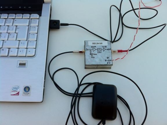
What they have done is use their open source GNSS software receiver program with a RTL-SDR connected to an active GPS antenna. An active GPS antenna requires DC power to be passed to the LNA in the GPS antenna through the antenna connection, so a Bias-T network is required to ensure DC power does not enter the RTL-SDR dongle.
Over on YouTube user taroz1461 shows real time GPS positioning done in software using a BladeRF. The BladeRF is a ~$400 software defined radio which similar specs to the HackRF and compared to the RTL-SDR is capable of receiving much larger bandwidths and transmitting.
Michele from Michele’s GNSS blog has posted his results with using a modified R820T RTL-SDR with Temperature Controlled Oscillator (TCXO) for GPS reception and decoding. The RTL-SDR is capable of tracking GPS even without TCXO but improved performance can be expected with a more stable oscillator. He notes that the R820T with it’s 3.57 MHz IF is ideally suited for GPS reception when combined with an active GPS antenna. Using this setup he was able to track GPS satellites and the Galileo E1B/C GNSS satellites as well.
Michele modified his R820T RTL-SDR with a 28.8 MHz TCXO he obtained from a friend. It is however possible to purchase modified TCXO R820T dongles directly from the 1090mhz webstore.
Modified TCXO R820T RTL-SDR used for GPS reception.
The RTLSDR scanner software has been updated and now supports connection to an external GPS receiver. With a GPS receiver attached to a laptop, the RTL-SDR can be used to make signal strength maps by driving around in a car and monitoring the radio spectrum with RTLSDR Scanner running. The signal strength map can then be viewed in Google Earth, a GIS program or any image viewer.
Recently we posted how RTLSDR Scanner has been updated to allow interfacing with a GPS device. This allows you to make signal strength maps by driving around and recording both signal strength and GPS location together.
Over on his blog “RTL-SDR DX” dewdude has been exploring the reception and decoding of Differential GPS (DGPS) signals. DGPS signals are transmitted by government authorities in the long wave band at around 300 kHz. These beacons are used to dramatically improve the accuracy of GPS (Global Positioning System) devices from their default accuracy of about 15 m down to about 10 cm. Unlike GPS signals which originate from satellites, the DGPS signal is terrestrial based and is broadcast from multiple known fixed positions. The signal itself contains information about the difference between the DGPS stations received GPS position and it’s known exact position. These differences can be used to correct other GPS receivers that receive DGPS signal.
By using his RTL-SDR (with upconverter or HF modification) dewdude was able to receive the DGPS beacon in SDR#. Then by piping the output audio into SpectrumLab’s DGPS decoder he was able to decode the data contained within the DGPS signal. His post contains a tutorial showing how to set up SpectrumLab to decode DGPS. If you’re interested in hearing what a DGPS signal sounds like, dewdude has uploaded a sound sample at the bottom of another post of his.
Decoding Differential GPS (DGPS) signals in SpectrumLab
Following on from our last post where dewdude showed how to decode DGPS signals, Frank K2NCC has uploaded a video on YouTube showing DGPS decoding in action. In his video Frank uses an Airspy plus ham-it-up upconverter, a Sirio discone antenna and for software he uses SDR# with audio piped into MultiPSK for decoding.
In the video you can clearly see the decoded DGPS messages showing the pseudorange corrections and station numbers. To decode DGPS with MultiPSK you will need to use the paid version which costs approximately $50 USD, however in the free version the DGPS will run for 5 minutes each time MultiPSK is opened before expiring.
Below is an example of a decoded message.
24/03/2015 02:06:09
Message type        : 9 (GPS partial correction set)
Station number      : 172 (Appleton WA USA 300.0 Khz TXID 871 100bps)
Z-count             : 4215 ( 42 mn 9.0 s )
Sequence count      : 2le factor=0.3)

Sat. ID|SF|UDRE|Pseudorange corr.  |Range rate corr.|IOD|CRC
25     |0 |1-4m|      -7.68 m      |   0.000 m/s    |62 |OK
31     |0 |1-4m|       1.54 m      |   0.000 m/s    |27 |OK
32     |0 |1-4m|       0.70 m      |   0.000 m/s    |99 |Error
Over on his blog /dev/thrash RTL-SDR experimenter Elia has been attempting to build an antenna to receive Global Positioning System (GPS) signals with his RTL-SDR. After doing some research he decided to build a Skew Planer Wheel antenna which he tuned for the GPS L1 frequency at 1575.42 MHz. A Skew Planar Wheel antenna is circularly polarized omnidirectional antenna which can be built out of wire. It is well suited to receiving signals from low earth orbiting (LEO) satellites such as the GPS satellites.
Elia later tested his antenna with a commercial GPS receiver circuit and was able to obtain a GPS fix.
Skew Planar Wheel Antenna on the RTL-SDR for receiving GPS.
At this years Defcon 2015 conference researcher Lin Huang from Qihoo 360 presented her work on spoofing GPS signals. Qihoo 360 is a Chinese security company producing antivirus software. Lin works at Qihoo as a security researcher where her main job is to prevent their antivirus software and users from becoming vulnerable to wireless attacks. Her research brought her to the realm of GPS spoofing, where she discovered how easy it was to use relatively low cost SDRs like a USRP B210/BladeRF/HackRF to emulate GPS signals which could allow a wireless attacker to manipulate the GPS on smartphones and cars.
Previous attempts at GPS spoofing have all used more expensive custom hardware. One attempt in 2013 allowed university researchers to send a 213-foot yacht off course, and it is suspected that hackers from the Iranian government have used GPS spoofing to divert and land an American stealth drone back in 2011.
In Lin’s presentation she shows how she was able to trick a smartphone into thinking it was in a different location. In addition she writes how this method could be used to trick the phone into changing it’s time, as many smartphones will periodically refresh the clock accuracy by using GPS satellites. She also shows how she was able to bypass a DJI drones forbidden area no fly zone policy. DJI drones come with a feature where the engines will not power up if the on board GPS detects that it is in a no drone fly zone. By spoofing the GPS she was able to get the drone to power up inside a no fly zone in Beijng.
To receive GPS e.p. uses one of our RTL-SDR blog units (back in stock soon!) with the bias tee enabled which is used to power a cheap 5V active GPS antenna. For software he uses GNSS-SDRLIB and RTKLIB which runs on Windows. Using the RTL-SDR, GPS antenna and the decoding software he was able to get his current position to within about 5 meters of accuracy.
In his blog post e.p. shows a step by step guide on how to install and use the Windows software. In later posts he also shows how to install and use another program called GNSS-SDR which runs in Linux and can also be used to acquire GPS fixes with an RTL-SDR dongle.
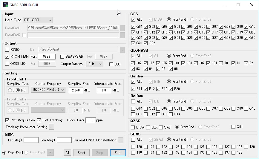
The GNSS-SDRLIB GUI setup screen.
To illustrate the software in action e.p. has also uploaded a video to YouTube which is shown below.
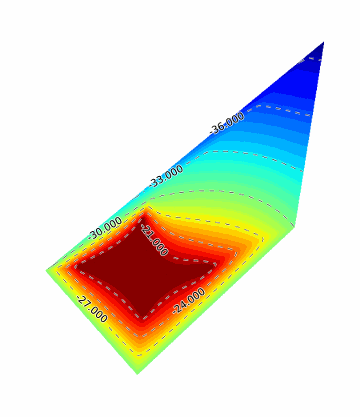
If you were to try to simply spot a GPS signal at 1.575 GHz in the spectrum on a waterfall in a program like SDR# you would probably fail to see anything. This is because GPS signals are very weak, and operate below the thermal noise floor. Only through clever processing algorithms can the actual signal be recovered.
With real data passed through the fast autocorrelation block he is able to observe GPS signal peaks that occur every millisecond. E.p. explains the reason for this:
Why every millisecond? The coarse/acquisition code for GPS (C/A) has a period of 1023 chips which are transmitted at a rate of 1.023 MBit/s. This results in period of 1 millisecond. BAM!
Over on the SDRGPS blog Philip Hahn and fellow aerospace engineer Paul Breed have been working together to try and use an RTL-SDR to help get accurate GPS data for tracking small high powered rockets. They write that their end goal is to be able to “track high power rockets in high acceleration / speed / altitude environments”.
In their latest attempt they launched a rocket with an RTL-SDR on board with it capturing GPS data to be later processed with GNSS-SDR. The goal was to get a GPS fix throughout the flight. Unfortunately they found that a good fix was only obtained while the rocket was on the ground, and not much data was obtained while it was in the air. They write that they suspect that the fault lies in the vibration in the rocket which can affect the frequency stability of the crystal oscillator, or in the GPS satellite tracking loop algorithm.
They still hope to be able to get some usable information from the flight by trying other algorithms on the data, but they are also seeking advice from anyone who might know how to help them, so please contact them if you know anything that may help.
Back in April we posted about Philip Hahn and Paul Breed’s experiments to use an RTL-SDR for GPS logging on their high powered small rockets. As GPS is owned by the US military, a standard GPS module cannot be used on a rocket like this, as they are designed to fail if the GPS device breaches the COCOM limit, which is when it calculates that it is moving faster than 1,900 kmph/1,200 mph and/or higher than 18,000 m/59,000 ft. The idea is that this makes it harder for GPS to be used in non-USA or home made intercontinental missiles. As SDR GPS decoders are usually programmed in open source software, there is no need for the programmers to add in these artificial limits.
In their last tests they managed to gather lots of GPS data with an RTL-SDR, but were only able to decode a small amount of it with the GNSS-SDR software. In this post Philip discoversa flaw in the way the GNSS-SDR performs acquisition and retrackingthat GNSS-SDR decodes in such a way that makes it difficult to obtain a location solution with noisy high-acceleration data. By using a different GPS implementation coded in MATLAB, he was able to get decoded GPS data from almost the entire ascent up until the parachutes deploy. Once the parachutes deploy the GPS has a tough time keeping a lock as it sways around. His post clearly explains the differences in the way the code is implemented in GNSS-SDR and in the MATLAB solution and shows why the GNSS-SDR implementation may not be suitable for high powered rockets.
In addition, they write that while the flight was just under the artificial COCOM GPS fail limits for speed and height, the commercial GPS solution they also had on board failed to collect data for most of the flight too. With the raw GPS data from the RTL-SDR + some smart processing of it, they were able to decode GPS data where the commercial solution failed.
GPS data acquired from the RTL-SDR on the rocket (blue line shows solution from MATLAB code, yellow shows GNSS-SDR solution, and red shows commercial GPS receiver solution).
In previous posts we showed how Phillip Hahn had been trying to use his RTL-SDR as a GPS receiver on a high powered rocket in order to overcome the COCOM limits which prevent commercial GPS devices from operating when moving faster than 1,900 kmph/1,200 mph and/or higher than 18,000 m/59,000 ft.
In order to test future flights with the RTL-SDR GPS receiver, Phillip has been simulating GPS rocket trajectory signals and using his LimeSDR. The RTL-SDR then receives the simulated GPS signals which are then fed into SoftGNSS for decoding. The simulation simulates the Japanese SS-520-4 rocket which is a 32′ long, 2′ diameter small high powered rocket capable of putting loads like cubesats into orbit affordably. Using the simulated data Phillip is able to calculate the trajectory and see all the motor burns in the velocity profile.
While Phillip intends to use the RTL-SDR on a similar rocket in the future, he notes that the simulation does not take into account problems such as thermal noise, or RF interference, rocket jerk, satellite occlusion and vibration problems.
LimeSDR Simulated GPS Rocket Trajectory Received with RTL-SDR.
The RTL-SDR can be used to receive, decode and plot Global Positioning System (GPS) data in real time. To do this the RTL-SDR must be connected to a GPS antenna.
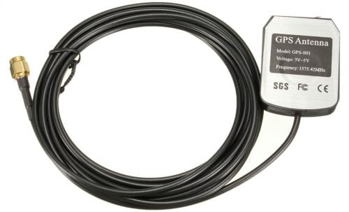
Extremely cheap $5 or less active GPS antennas with SMA connectors can be found on eBay, Amazon or Aliexpress. These GPS antennas contain a small ceramic patch antenna, a low noise amplifier and a GPS filter. In order to power the LNA in the antenna, you’ll need to have an RTL-SDR with bias tee. Our RTL-SDR.com V3 dongles have this feature built in, but if you don’t have a V3 you could also use a homebrew 5V external bias tee module or hack it into a standard RTL-SDR if you desired.
Also note that most standard R820T/2 RTL-SDRs fail to receive after a few minutes at frequencies above about 1.3 GHz due to heat issues. Our RTL-SDR.com V3 dongles don’t have this problem in most climates thanks to the metal case cooling and improved thermal design on the PCB. If you experience this problem it can also be alleviated by using the special L-Band RTL-SDR drivers.
A typical $3 GPS antenna
The main GPS frequency is 1.575420 GHz, but most of this signal is very weak and below the noise floor. If you were try to view the spectrum of GPS in SDR# you will find that you won’t see much other than perhaps a very weak hump. Only through clever signal processing is such a weak signal actually recovered. Below we show screenshots of the GPS spectrum as seen by an RTL-SDR and more wideband Airspy R2 SDR.
GPS RTL-SDR
GPS Airspy
The following tutorial shows how to receive and decode GPS signals and get a coordinate on a map of your location, using only an RTL-SDR dongle (with bias tee) and GPS antenna. This tutorial is based heavily on Philip Hahn’s blog post at sdrgps.blogspot.com/2015/12/first-proof-of-concept-gps-fix-in.html.
Download GNSS-SDRLIB from github.com/taroz/GNSS-SDRLIB. On GitHub click on the green “Clone or download” button on the right and then click “Download ZIP”. Extract the zip file into a convenient folder on your PC. If you want to use the modified L-band drivers, copy the modified rtlsdr.dll into the the bin folder.
Make sure your RTL-SDR is plugged in, and that the bias tee has been activated (V3 software for activating the bias tee, see feature 2).
In the GNSS-SDRLIB folder, open gnss-sdrgui.exe. This will be stored in the bin subfolder.
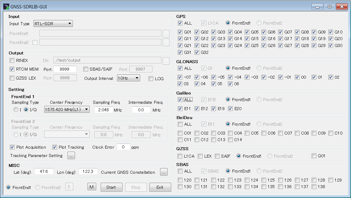
Now set the following parameters:
Change the Input Type to RTL-SDR
Place a check next to RTCM MSM , and set the Port to 9999.
Ensure that “Output Interval” is set to 10Hz.
Ensure that “Plot Acquisition” and “Plot Tracking” are both checked.
Under “MISC” optionally enter your approximate latitude and longitude to help with getting an initial lock..
Under the GPS, GLONASS and Galileo headings ensure that the “ALL”
Apply appropriate settings in GNSS-SDRLIB GUI
Press Start. A bunch of command windows will begin opening and closing for a few seconds. After that, a bunch of gnuplot graph windows will open up. These can be ignored.
Next go to the extracted RTK-NAVI folder, and enter the bin directory. Open the rtlnavi.exe file.
Click on the “I” button in the upper right region.
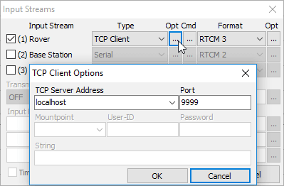
Place a check mark next to (1) Rover, and change the “Type” to TCP Client, and the “Format” to RTCM3. Click on the button with three dots under the leftmost “Opt” and set the “TCP Server Address” to localhost, and the “Port” to 9999. Press the OK button to exit the two windows.
Set the input stream
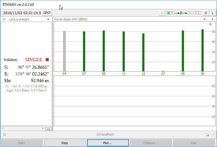
Now press Start in RTK-NAVI.
You should now see several bars in the top graph. These bars show GPS signal strengths for satellites. After a short time you should see a solution in the left panel which will be your current coordinates. If no solution ever comes, try respositioning your GPS antenna for a better view of the sky, and double checking that the bias tee is activated. Sometimes simply restarting GNSS-SDRLIB can fix no solution being found.
Check reception and wait for GPS lock solution.
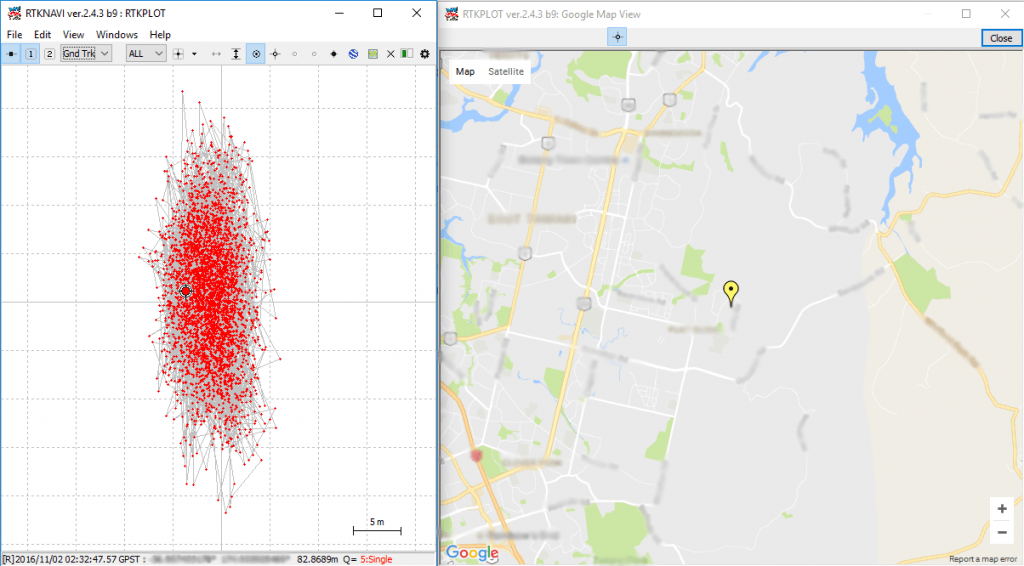
In RTK-NAVI click on the “Plot” button. This will open a positional plot of the recorded coordinates. To view your position on a Google map, click View → Google Map View. If everything is working correctly you should now be seeing an accurate marker of your current location.
Over on his blog /dev/thrash RTL-SDR experimenter Elia has been attempting to build an antenna to receive Global Positioning System (GPS) signals with his RTL-SDR. After doing some research he decided to build a Skew Planer Wheel antenna which he tuned for the GPS L1 frequency at 1575.42 MHz. A Skew Planar Wheel antenna is circularly polarized omnidirectional antenna which can be built out of wire. It is well suited to receiving signals from low earth orbiting (LEO) satellites such as the GPS satellites.
Elia later tested his antenna with a commercial GPS receiver circuit and was able to obtain a GPS fix.
Skew Planar Wheel Antenna on the RTL-SDR for receiving GPS.
At this years Defcon 2015 conference researcher Lin Huang from Qihoo 360 presented her work on spoofing GPS signals. Qihoo 360 is a Chinese security company producing antivirus software. Lin works at Qihoo as a security researcher where her main job is to prevent their antivirus software and users from becoming vulnerable to wireless attacks. Her research brought her to the realm of GPS spoofing, where she discovered how easy it was to use relatively low cost SDRs like a USRP B210/BladeRF/HackRF to emulate GPS signals which could allow a wireless attacker to manipulate the GPS on smartphones and cars.
Previous attempts at GPS spoofing have all used more expensive custom hardware. One attempt in 2013 allowed university researchers to send a 213-foot yacht off course, and it is suspected that hackers from the Iranian government have used GPS spoofing to divert and land an American stealth drone back in 2011.
In Lin’s presentation she shows how she was able to trick a smartphone into thinking it was in a different location. In addition she writes how this method could be used to trick the phone into changing it’s time, as many smartphones will periodically refresh the clock accuracy by using GPS satellites. She also shows how she was able to bypass a DJI drones forbidden area no fly zone policy. DJI drones come with a feature where the engines will not power up if the on board GPS detects that it is in a no drone fly zone. By spoofing the GPS she was able to get the drone to power up inside a no fly zone in Beijng.
To receive GPS e.p. uses one of our RTL-SDR blog units (back in stock soon!) with the bias tee enabled which is used to power a cheap 5V active GPS antenna. For software he uses GNSS-SDRLIB and RTKLIB which runs on Windows. Using the RTL-SDR, GPS antenna and the decoding software he was able to get his current position to within about 5 meters of accuracy.
In his blog post e.p. shows a step by step guide on how to install and use the Windows software. In later posts he also shows how to install and use another program called GNSS-SDR which runs in Linux and can also be used to acquire GPS fixes with an RTL-SDR dongle.
The GNSS-SDRLIB GUI setup screen.
To illustrate the software in action e.p. has also uploaded a video to YouTube which is shown below.